Dairy Processing
26 Production and Utilization of Steam and Refrigeration
This section will describe the production and utilization of both steam and refrigeration, two utilities absolutely essential to the operation of a dairy processing plant.
Steam Production and Utilization
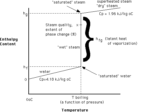
The diagram below helps to explain the various principles involved in the thermodynamics of steam. It shows the relationship between temperature and enthalpy (energy or heat content) of water as it passes through its phase change.

The reference point for enthalpy of water and steam is 0oC, at which point an enthalpy value of 0 kJ/kg is given to it (but of course water at 0o has a lot of energy in it, which is given up as it freezes – it’s not until 0K, absolute zero, when it truly has no enthalpy!). As we increase the temperature of water, its enthalpy increases by 4.18 kJ/kg oC until we hit its boiling point (which is a function of its pressure – the boiling point of water is 100oC ONLY at 1 atm. pressure). At this point, a large input of enthalpy causes no temperature change but a phase change, latent heat is added and steam is produced. Once all the water has vaporized, the temperature again increases with the addition of heat (sensible heat of the vapour).
Steam Production and Distribution
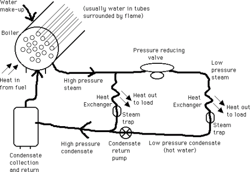
Steam is produced in large tube and chest heat exchangers, called water tube boilers if the water is in the tubes, surrounded by the flame, or fire tube boilers if the opposite is true. The pressure inside a boiler is usually high, 300-800 kPa. The steam temperature is a function of this pressure. The steam, usually saturated or of very high quality, is then distributed to the heat exchanger where it is to be used, and it provides heat by condensing back to water (called condensate) and giving up its latent heat. The temperature desired at the heat exchanger can be adjusted by a pressure reducing valve, which lowers the pressure to that corresponding to the desired temperature. After the steam condenses in the heat exchanger, it passes through a steam trap (which only allows water to pass through and hence holds the steam in the heat exchanger) and then the condensate (hot water) is returned to the boiler so it can be reused. The following image is a schematic of a steam production and distribution cycle.

Refrigeration

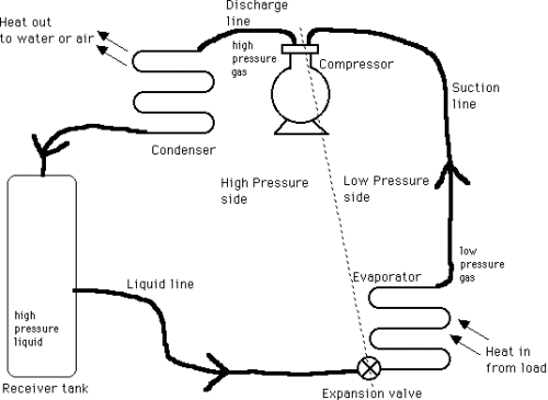
Mechanical refrigerators have four basic elements: an evaporator, a compressor, a condenser, and a refrigerant flow control (expansion valve). A refrigerant circulates among the four elements changing from liquid to gas and back to liquid.
In the evaporator, the liquid refrigerant evaporates (boils) under reduced pressure and in doing so absorbs latent heat of vaporization and cools the surroundings. The evaporator is at the lowest temperature in the system and heat flows to it. This heat is used to vaporize the refrigerant. The temperature at which this occurs is a function of the pressure on the refrigerant: for example if ammonia is the refrigerant, at -18oC the ammonia pressure required is 1.1 kg/sq. cm. The part of the process described thus far is the useful part of the refrigeration cycle; the remainder of the process is necessary only so that the refrigerant may be returned to the evaporator to continue the cycle.
The refrigerant vapour is sucked into a compressor, a pump that increases the pressure and then exhausts it at a higher pressure to the condenser. For ammonia, this is approx. 10 kg/sq. cm. To complete the cycle, the refrigerant must be condensed back to liquid and in doing this it gives up its latent heat of vaporization to some cooling medium such as water or air. The condensing temperature of ammonia is 29oC, so that cooling water at about 21oC could be used. In home refrigerators, the compressed gas (not ammonia) is sent through the pipes at the back, which are cooled by circulating air around them. Often fins are added to these tubes to increase the cooling area. The gas had to be compressed so that it could be condensed at these higher temperatures, using free cooling from water or air.
The refrigerant is now ready to enter the evaporator to be used again. It passes through an expansion valve to enter into the region of lower pressure, which causes it to boil and absorb more heat from the load. By adjusting the high and low pressures, the condensing and evaporating temperatures can be adjusted as required.

